As compounding, reactive extrusion, and high-performance polymer processes become more complex, a surface-level understanding of extrusion machinery is no longer sufficient for procurement and engineering teams. Specifying the wrong extruder configuration—whether due to incorrect shear rates, improper thermal zones, or mismatched screw geometries—results in material degradation, inconsistent throughput, and accelerated equipment wear. You cannot afford to guess when configuring these systems. A deep technical understanding of internal mechanics, including mechanical transport, friction, and thermal control, is the mandatory first step before evaluating vendors or commissioning a custom twin screw extrusion solution. We must look at the exact physics happening inside the barrel to make informed equipment decisions.
- Mechanics Dictate Application: The interaction between the two rotating screws (intermeshing, self-wiping, and positive displacement) directly governs material mixing, shear, and residence time distribution (RTD).
- Geometry is Critical: The choice between a conical twin screw extruder and a parallel system fundamentally alters pressure generation and is dictated by the specific polymer or compound being processed.
- Component Durability Matters: High-torque applications require specialized metallurgy; selecting a reliable twin screw and barrel supplier is as critical as the initial machine design.
- Vendor Evaluation: Partnering with a qualified twin screw extruder manufacturer requires vetting their ability to customize L/D ratios, thermal zones, and control systems to your specific success criteria.
The Core Working Principle of a Twin Screw Extruder
Mechanical Transport and Positive Displacement
The dual-screw setup creates closed or semi-closed cavities that force material forward. This geometry enables positive displacement conveying conditions. From the feed throat through the barrel, positive displacement prevents material stagnation, a common issue in single-screw systems where material can stick to the screw and rotate without moving forward. The twin screw extruder profile overcomes the friction-drag dependency of single-screw systems, ensuring consistent output under high pressure. When processing highly filled compounds or low-friction polymers, this positive pumping action is what keeps the line running without surging.
Engineers rely on this mechanism to maintain tight control over the residence time distribution. Because the material is pushed from one C-shaped chamber to the next, you get a first-in, first-out flow profile. This is highly beneficial for reactive extrusion processes where reaction times must be strictly controlled to prevent over-crosslinking or degradation.
Modular Screw Architecture: Splined Shafts and Segmented Elements
Modern modular screws assemble individual segments on splined shafts. These segments include conveying, kneading, mixing, and reverse elements. This modular design enables engineers to configure a system tailored to specific shear-sensitivity and melting profiles. Specialized elements, such as distributive mixing elements, neutral kneading blocks, and restriction rings, perform distinct functions within the process. You can swap out a high-shear kneading block for a distributive gear mixing element if your formulation changes from a tough engineering plastic to a shear-sensitive elastomer.
The splined shaft itself is designed to handle massive torque loads. High-torque shafts often use an involute spline design to distribute the rotational force evenly across the inner diameter of the screw elements. This prevents shaft twisting or element cracking when processing high-viscosity melts at low temperatures.
Friction, Shear, and Thermal Control
Extrusion balances mechanical shear and external thermal control. Screw rotation and kneading blocks generate friction, while barrel heaters and coolers manage external temperatures. Specific screw elements, like kneading blocks and reverse elements, are configured to control the exact amount of shear energy imparted to the material. Independent cooling and heating circuits along the barrel prevent runaway viscous dissipation through precise thermal zoning. If you run a high-speed compounding line, the mechanical shear often generates more heat than the process requires, making the barrel cooling system the primary temperature control mechanism.
We use water or oil cooling channels drilled close to the inner barrel wall to extract this excess heat rapidly. The balance between the screw RPM, the aggressiveness of the kneading blocks, and the efficiency of the cooling system determines the final melt temperature. Getting this wrong leads to polymer degradation, off-gassing, and poor mechanical properties in the final product.
The Self-Wiping Mechanism
The kinematic interaction features the flight of one screw wiping the root of the other with close clearance. This self-wiping action prevents material buildup on barrel walls. It ensures uniform residence time distribution and minimizes thermal degradation of heat-sensitive polymers. When processing materials that tend to crosslink or burn if left stagnant, this continuous surface renewal is what keeps the extruder from plugging up.
The clearance between the screws is typically engineered down to fractions of a millimeter. This tight tolerance requires precision machining and robust thrust bearings to prevent the screws from deflecting and crashing into each other under high pressure. The self-wiping profile also aids in color changeovers, as the screws effectively clean themselves, reducing the amount of purge compound needed between runs.
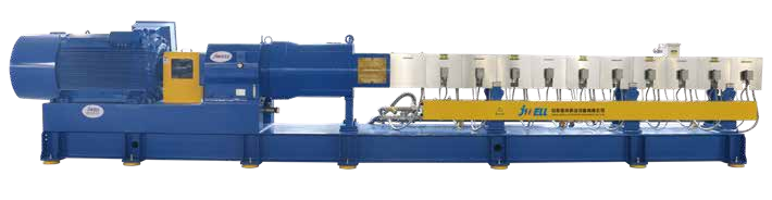
Structural Variations: Evaluating Extruder Types for Your Application
Co-Rotating vs. Counter-Rotating Parallel Twin Screw Systems
Co-rotating parallel twin screw systems utilize high-speed, high-shear mechanics ideal for compounding, filler dispersion, alloying, and reactive extrusion. Material transfers in a figure-eight pattern between the screws, maximizing surface area renewal. This aggressive mixing is what you need to break down agglomerates in color masterbatches or disperse glass fibers into a nylon matrix. The high RPM capabilities allow for massive throughputs on relatively small machine footprints.
A counter-rotating parallel twin screw relies on low-shear, high-pressure mechanics where material is conveyed in closed, C-shaped chambers. This makes it suitable for profile extrusion, pipe extrusion, and processing thermally sensitive materials like rigid PVC formulations. The counter-rotating action acts like a positive displacement gear pump, building immense die pressure without generating excessive shear heat. This is why you see them dominating the heavy pipe and wide sheet extrusion sectors.
Conical Twin Screw Extruder Mechanics
A conical twin screw extruder features a tapered screw design, with a larger diameter at the feed end and a smaller diameter at the discharge end. The large volume capacity in the feed zone allows for processing low bulk density materials and dry blends. The small diameter in the discharge zone reduces linear velocity and shear heat, allowing for gradual, high-pressure build-up. This configuration is the preferred standard for high-output PVC profiles and pipe manufacturing.
The geometry of the conical screws naturally compresses the material as it moves forward. This eliminates the need for aggressive compression ratios in the screw flight design, further protecting shear-sensitive polymers. The massive thrust bearings required to handle the backpressure are housed in the wider rear section of the gearbox, providing excellent mechanical stability and long operational life.
Intermeshing vs. Non-Intermeshing Designs
Intermeshing screws offer tight clearance and high self-wiping capabilities. Non-intermeshing designs provide highly distributive, lower-shear mixing. Matching these designs to specific material viscosities and mixing requirements is essential, differentiating between highly filled polymers and low-viscosity elastomer blending. Non-intermeshing extruders are often used in devolatilization applications where you need a large surface area of the melt exposed to vacuum without imparting high shear.
In an intermeshing setup, the flights of one screw penetrate the channels of the other. This creates high-shear regions at the apex where the screws meet. In a non-intermeshing setup, the screws are positioned further apart, allowing material to flow freely between the two shafts. This results in a much gentler mixing action, suitable for blending highly viscous materials with low-viscosity additives without causing phase separation.
Industrial Application Matrix
| Application | Recommended Extruder Type | Key Operational Benefit |
| Compounding & Masterbatch | Co-rotating parallel systems | High shear, excellent dispersive mixing, rapid surface renewal. |
| Thermally Sensitive Profile Extrusion (PVC) | Conical or counter-rotating parallel systems | Low shear heat generation, high positive displacement pressure. |
| Devolatilization & Solvent Removal | Multi-vented, high L/D parallel systems | Large melt surface area exposure, multiple vacuum zones. |
| Food & Pharmaceutical Extrusion | Sanitary-grade co-rotating systems | Self-wiping cleanability, precise temperature control. |
Anatomy of the Extrusion Process: Features to Outcomes
Feeding and Hopper Dynamics
Introducing solid material into the extruder requires precise mechanics at the interface of the feed throat and the screw flight. Feed throat cooling jacket designs prevent premature melting and bridging. If the feed throat gets too hot, the polymer pellets will melt and stick to the walls, blocking the flow of material and starving the extruder. We run chilled water through the feed throat casting to maintain a crisp temperature boundary.
Gravimetric (loss-in-weight) feeders are often necessary over volumetric feeders for maintaining precise formulation ratios in continuous processing. Volumetric feeders assume a constant bulk density, which is rarely true for regrind or highly filled powders. Gravimetric feeders constantly weigh the material being fed and adjust the auger speed to maintain a strict mass flow rate, ensuring your final compound meets exact specifications.
Melting and Plasticizing Zones
The solid bed is broken down through a combination of conductive heat from the barrel and mechanical shear from kneading blocks. The configuration of the screw profile in this zone dictates the speed and homogeneity of the polymer melt. We typically use a series of forward-conveying elements to build pressure, followed by a restrictive kneading block section that forces the solid pellets to rub against each other and the barrel wall.
This frictional heat is what actually melts the polymer in a high-speed twin screw setup. The barrel heaters are mostly there to bring the machine up to temperature before startup and to maintain the setpoint if the mechanical shear isn't enough. Designing this zone requires balancing the need for rapid melting against the risk of localized overheating.
Venting and Degassing (Devolatilization)
Atmospheric and vacuum venting zones utilize specialized forward-conveying elements to lower pressure and create a thin material film. They remove moisture, trapped air, residual monomers, and volatile byproducts before the die to prevent structural defects in the final product. If you don't extract these gases, they will expand as the melt exits the die, causing foaming, surface defects, and a massive drop in mechanical strength.
- The screw profile transitions to a deep-flighted, high-pitch conveying element under the vent port.
- This sudden increase in free volume drops the melt pressure to near zero.
- The polymer forms a thin film on the barrel wall and screw root, maximizing surface area.
- A vacuum pump pulls the volatile gases out through the vent port.
- The screw profile then transitions back to a restrictive element to rebuild pressure for the next zone.
Pumping, Die Shaping, and Pelletizing
The final metering zone stabilizes pressure to overcome the resistance of the die. The extruder interfaces with melt filtration systems (screen changers) and various die heads (strand, underwater, sheet, profile) to achieve the final product geometry. The screw elements in this zone are designed to minimize shear while maximizing pumping efficiency. We want a steady, pulsation-free flow of melt entering the die.
Screen changers are installed between the extruder and the die to filter out unmelted particles, degraded polymer, and foreign contaminants. The pressure drop across the screen pack must be carefully monitored. As the screens clog, the backpressure increases, which can shift the melting profile further back into the extruder and alter the entire process dynamic.
Specifying a Custom Twin Screw Extrusion Solution
L/D Ratio (Length to Diameter) and Residence Time
Calculate and specify the L/D ratio based on the complexity of the compounding task. Standard melting, venting, and profile extrusion typically require 24:1 to 36:1 L/D. Advanced compounding, multi-point feeding, liquid injection, and deep devolatilization demand 40:1 to 48:1+ L/D. Longer barrels offer better mixing and multiple operations but carry a risk of degradation and high torque requirements.
You cannot just buy the longest barrel available and expect good results. A barrel that is too long for a simple compounding task will subject the polymer to unnecessary heat history, degrading its physical properties. Conversely, a barrel that is too short will not provide enough residence time for proper dispersive mixing or devolatilization. You must map out every unit operation (feeding, melting, mixing, venting, pumping) and assign the necessary L/D to each section.
Metallurgy, Barrel Liners, and Wear Resistance
Abrasive and corrosive wear in the barrel and screw elements requires careful material selection. Evaluate base materials like nitrided steels, tool steels, and PM (powder metallurgy) steels. Consider coatings and liners such as bimetallic liners, chrome plating, and physical vapor deposition (PVD) coatings. Segmented barrels with replaceable wear sleeves offer modularity over solid barrels. When processing 30% glass-filled nylon, standard nitrided barrels will wear out in months. You need PM tool steel elements and bimetallic barrel liners to survive that level of abrasion.
Selecting a reliable twin screw and barrel supplier ensures you get the right metallurgy for your specific formulation. Corrosive wear from fluoropolymers or halogenated flame retardants requires high-nickel alloys like Hastelloy or Inconel. The initial cost of these premium materials is offset by the massive reduction in downtime and replacement parts.
Scalability: From Lab-Scale "Scientific" Extruders to Production
Scaling up from lab-scale scientific extruders to full production requires applying strict engineering principles. Ensure the chosen configuration translates effectively to higher throughputs while maintaining material integrity. You cannot simply scale up the RPM and expect the same melt temperature. The surface-area-to-volume ratio changes drastically as you move from a 20mm lab extruder to a 75mm production machine.
Heat transfer becomes much less efficient on larger machines. The mechanical shear generated by the larger diameter screws will dominate the thermal profile. You must adjust the screw geometry, specifically the aggressiveness of the kneading blocks, to compensate for this shift in thermodynamics. Partnering with an experienced twin screw extruder manufacturer is critical during this scale-up phase to avoid costly production failures.
- Audit your current material formulations to determine exact shear and thermal limits.
- Map out the required unit operations to calculate the precise L/D ratio needed.
- Specify the metallurgy for screws and barrels based on the most abrasive or corrosive compound you plan to run.
- Demand a pilot-scale trial from the manufacturer to validate the screw profile before signing off on the final machine build.
FAQ
Q: What is the main advantage of a twin screw extruder over a single screw?
A: It provides positive displacement, preventing material stagnation, and offers superior mixing, shear control, and self-wiping capabilities. This allows for processing complex formulations, highly filled compounds, and reactive extrusions that would fail in a single screw setup.
Q: When should I use a conical twin screw extruder?
A: It is ideal for thermally sensitive materials like PVC. The large feed zone handles low bulk density powders, while the tapered design reduces shear heat at the discharge end, allowing for high-pressure profile extrusion without degrading the polymer.
Q: What does the L/D ratio mean?
A: The Length to Diameter ratio indicates the barrel's length relative to its internal diameter. It determines the available residence time and the number of unit operations (like venting or side feeding) you can perform along the barrel.
Q: How does self-wiping work?
A: The flights of one screw closely pass the root of the other as they rotate. This tight clearance continuously scrapes material off the metal surfaces, preventing polymer stagnation, degradation, and buildup on the barrel walls.
Q: Why are modular screws important?
A: They allow engineers to customize the screw profile by sliding different conveying, kneading, and mixing elements onto a splined shaft. This flexibility lets you reconfigure the machine for different polymers or compounding tasks without buying a whole new screw.


