The process conditions during spinning determine the changes in fibers during the shaping process, significantly impacting the spinnability, structure and properties of the wound yarn, and the characteristics of the finished yarn. The properties of the finished yarn are thus greatly influenced by these conditions.
01 Melt temperature (Tm)
The melt temperature, also known as the spinning temperature, must be properly controlled to ensure good spinnability and excellent physical and mechanical properties of the finished yarn. The melt temperature should fully melt the chips while preventing severe thermal degradation of the polyester macromolecules. Therefore, for chips with a characteristic viscosity in the range of 0.64 to 0.66, the melt temperature is generally recommended to be controlled between 285 and 290°C. If it exceeds 300°C, the polyester macromolecules will undergo rapid thermal degradation. Within the aforementioned temperature range, as the temperature increases, the flow viscosity of the melt gradually decreases, leading to improved uniformity and rheological properties, thereby enhancing spinnability.
The pre-orientation degree of the wound yarn (birefringence index n) decreases, the cross-sectional uniformity decreases, and the spinning tension also decreases. The maximum stretch ratio and natural stretch ratio of the wound yarn increase. After stretching, the strength and elongation of the stretched yarn also show an increasing trend. Therefore, as long as the melt viscosity does not decrease significantly, the temperature can be kept as high as possible.
However, the melt temperature should not be too high. Excessively high temperatures can exacerbate the degradation of polyester macromolecules, leading to reduced or fluctuating screw pressure, which can cause fluctuations in the fiber solidification point, increased unevenness in the sliver, and higher rates of unevenness in dyeing, among other issues. Additionally, it may result in increased filaments from the injection head, more fluff and broken ends during winding, and excessive elongation of the finished product. In severe cases, the extruded filaments may appear discontinuous and be unable to wind properly.
The melt temperature also cannot be too low. If the temperature is too low, the excessive viscosity will increase the shear stress of the melt in the spinneret, causing melt breakage and resulting in poor spinnability. When the temperature is below 280°C, the strength and elongation of the spun filaments are both low. This type of filament is referred to as weak filament, which tends to produce fluff and broken ends during stretching, making operation difficult.
In actual production processes, the melt temperature often fluctuates, which can easily lead to color differences in the fibers. The temperature fluctuation is generally controlled within a range of ±1°C. It should be noted that different characteristics of polyester chips have varying intrinsic viscosities and melting points, so the selected melt temperature range should also differ accordingly. Generally, for an intrinsic viscosity variation of ±0.1, the melt temperature should change correspondingly by ±10°C.
The appropriateness of the selected melt temperature can be evaluated not only from the operation conditions of spinning and stretching, as well as the quality indicators of the finished yarn, but also by assessing the viscosity drop of the oil-free yarn. A Δn of less than 0.04, with minimal fluctuations, is desirable.
The melt temperature can be controlled by the temperatures of the screw extruder and the spinning box. Additionally, the effects of frictional heat generation should also be considered. Based on the fundamental functions of the screw, it can be divided into the feed section, compression section, and metering section. In practical use, to facilitate temperature control, the screw can be divided into several heating control zones.
02 screw extrusion pressure
Screw extrusion pressure refers to the melt pressure at the outlet of the screw extruder, which is measured and controlled by pressure sensors. The screw extrusion pressure is used to overcome the resistance of the melt in equipment such as pipes and mixers, ensuring that there is a certain melt pressure at the inlet of the metering pump.
According to literature reports, the pump inlet pressure must reach 2 MPa for the metering pump to accurately measure and output; otherwise, it may result in insufficient or fluctuating pump supply, causing the spun yarn to become thinner or uneven.
Taking the VC406A spinning machine as an example, when spinning 167 dtex filament at a speed of 1000 m/min, the pipeline resistance is 2.6 MPa, and at least 4.6 MPa of screw extrusion pressure is required on the spinning machine for normal production.
In actual production, it is necessary to control the pressure between 6.5 and 7.5 MPa. Although higher screw extrusion pressure is beneficial for spinning, excessively high pressure requires faster screw rotation, which increases the backflow of the melt within the extruder and raises energy consumption. If the pressure exceeds the equipment's pressure tolerance range, accidents may occur.
03 Pump Supply Volum
Pump supply volume refers to the mass of melt delivered by the metering pump per unit of time. The size of the pump supply volume directly affects the thickness of the spun yarn. The pump supply volume can be determined through calculation and then adjusted based on actual conditions. The calculation formula is as follows:
Q = DRV/(l0000 K)
In the formula, Q is the pump supply volume (g/min), D is the density of the finished yarn (dtex), R is the stretching ratio, v is the spinning speed (m/min), and K is the fiber contraction coefficient (commonly taken as 1.05 to 1.10). In actual production, the pump supply volume is not directly controlled; instead, it is achieved by controlling the pump's rotation speed. The pump's rotation speed can be calculated using the following formula:
N=Q/γηC
In the formula: n is the metering pump speed (r/min), Q is the pump supply volume (g/min), γ is the melt density (g/cm³), η is the metering pump efficiency (generally 98%), and C is the metering pump capacity (cm³/r).
The permissible speed for a general dosing pump is 15 to 40 r/min, with the optimal range being 20 to 30 r/min. If the calculated speed is outside this range, it can be adjusted by changing the specifications of the dosing pump
04 Component Pressure
Component pressure is used to overcome the resistance encountered by the melt as it passes through the filter layer and spinneret holes, and it is closely related to the uniformity of the fiber quality.
During high-pressure spinning, the component pressure ranges from 9.8 to 24.5 MPa, resulting in better quality of the wound yarn. As the usage time of the component increases, impurities in the filter layer gradually accumulate, leading to increasing resistance and continually rising component pressure. In terms of component pressure, the process mainly considers the initial pressure and the rate of pressure increase.
The initial pressure refers to the pressure measured 30 minutes after the new component has stabilized during spinning, also known as the starting pressure. It is related to the composition of the filter layer, the pump output, the melt temperature, and viscosity, and is generally set between 9.8 to 14.7 MPa.
The pressure increase rate refers to the degree of increase in component pressure per unit of time (hour or day) during normal use. The daily pressure increase rate should be less than 6%. A rapid increase in pressure can shorten the lifespan of the component. If the component pressure reaches a maximum of 30 MPa, it must be replaced. Continuing to use it may damage the dosing pump or cause deformation of the spinneret plate or material leakage.
05 Cooling Blowing Temperature, Humidity, and Wind Speed
When spinning filaments, side-blowing is generally used, with three main parameters: temperature, humidity, and wind speed (air volume). Additionally, there is the wind speed distribution on the surface of the side-blowing window.
The cooling blowing temperature is between 20 to 30°C. If the spinning speed increases, the air temperature should be appropriately lowered to accelerate cooling. Currently, a temperature of 28°C is commonly used.
The cooling blow should have a certain level of humidity to prevent static electricity generated by the friction of the filaments with dry air in the duct, reducing filament shaking and bouncing. It also helps maintain a constant indoor temperature, facilitating heat transfer and enhancing cooling of the filaments. Additionally, it affects the crystallinity, elongation, and moisture regain of the filaments. A relative humidity between 65% and 80% is acceptable, typically controlled at around 70%.
Wind speed (air volume) has a significant impact on the pre-orientation (birefringence) and stretch ratio of the wound yarn. As wind speed increases, birefringence of the wound yarn decreases, while the cold stretch ratio increases. This is due to better cooling effects at higher wind speeds, which shift the solidification point toward the spinneret, shortening the deformation zone and weakening the stretching orientation effect on the melt before solidification.
Additionally, higher wind speeds can improve dye uniformity and reduce variations in linear density, while also mitigating interference from outdoor airflow. However, if the wind speed exceeds a certain level, it can cause the filaments to shake and become turbulent, increasing the cooling effect on the spinneret surface and potentially leading to a rise in the variability of product quality indicators. The cooling wind speeds for filaments of different linear densities are shown in Table.
Table 9-2: Reference Table for Cooling Wind Spee |
Line Speed(dtex) | 50 | 76 | 167 |
Cooling Wind Speed Selection Range(m/s) | 0.25~0.30 | 0.30~0.35 | 0.40~0.50 |
Moreover, wind speed must be stable, as fluctuations can increase the unevenness of the filament diameter. This unevenness is one of the key causes of dyeing inconsistencies and variations in tensile strength. Wind speed distribution curves typically take three forms: uniform linear, curved, and S-shaped, with linear and curved being the most common. To maintain the temperature of the spinneret surface, some setups include a cooling zone within the spinning window, with the lower opening insulated using asbestos boards. During normal production, it is essential to properly position the insulation boards.
06 Winding Speed
Winding speed is an important factor affecting the pre-orientation of the wound yarn. The higher the winding speed, the greater the degree of pre-orientation, but the subsequent stretch ratio tends to be lower. While the spindle productivity increases with winding speed, it does not do so in a linear proportion.
Under optimal conditions, winding speed should be maximized, as this not only increases production efficiency but also improves yarn quality. According to available data, the optimal winding speed for conventional spinning is between 900 and 1200 m/min.
The ratio of winding speed to melt ejection speed is referred to as the spinneret stretch ratio. An increase in the spinneret stretch ratio results in a decrease in the subsequent stretch ratio. The spinneret stretch ratio can be calculated using Equation (9-9).
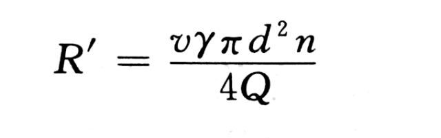
In the equation, R′R'R′ represents the spinneret stretch ratio, vvv is the winding speed (cm/min), γ\gammaγ is the melt density (g/cm³), ddd is the diameter of the spinneret hole (cm), nnn is the number of spinneret holes, and QQQ is the pump output (g/min).
07 Reciprocation Frequency of the Cross-moving Guide Yarn Device
The reciprocation frequency of the cross-moving guide yarn device determines the size of the bobbin winding angle and affects the winding tension, making it a key factor in achieving good winding formation. In production, the commonly used winding angle is typically between 6° and 7°. The reciprocation frequency can be calculated using Equation (9-10).
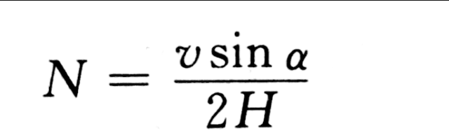
In the equation, NNN represents the reciprocation frequency (cycles/min), α\alphaα is the winding angle (°), HHH is the yarn guide stroke (m), and vvv is the winding speed (m/min).
To prevent poor winding formation caused by overlapping yarns, the reciprocation frequency of the cross-moving guide yarn device should be varied periodically. The range of variation is referred to as the amplitude, while the duration of the variation is called the period. The amplitude is typically set at ±15 to 25 cycles/min, and the period is generally between 15 to 25 seconds. When the winding speed increases, both the amplitude and the period should be appropriately reduced.
08 Roller Rotation and Oil Concentration
The amount of oil applied to the wound yarn directly determines the oil content of the finished multifilament. Higher oil concentration and faster roller rotation speed both lead to increased oil application. The amount of oil applied depends on the final use of the yarn: for woven yarns, it is 0.6% to 0.7%; for knitted yarns, 0.7% to 0.9%; and for elastic yarns, 0.5% to 0.6%. The roller rotation speed is typically between 10 and 20 r/min, with an oil concentration of 10% to 16%.
To ensure uniform oil application, the roller rotation speed and oil concentration must be coordinated. If the oil concentration increases and the roller speed decreases, the oil will have better splattering and diffusion properties but poorer adhesion. Conversely, if the oil concentration decreases and the roller speed increases, the splattering and diffusion properties will be poorer, while adhesion will improve.
The spinning oil must be prepared as an emulsion of a specific concentration before use. The prepared oil should be uniform and have strong transparency.


